EMT Conduit Smart Telescoping Pole Part 1: Force-Sensing
- EST - Austin

- Jan 9, 2022
- 9 min read
Updated: Jan 30, 2022
Introduction
This article is part of a series discussing methods for adding sensing capabilities to a DIY telescoping pole project made from EMT conduit.
Force sensing, in the context of a telescoping pole, refers to ability to measure the side/lateral load that is exerted at the tip of the pole. Having this capability can be useful for any kind of project where a DIY telescoping pole is needed:
Birdfeeder - Know when the feeder has been visited by a bird, according to when the pole has flexed.
Structural - A greenhouse, tent, or awning support can be monitored remotely, and give the user time to dismantle the structure and prevent collapse in inclement weather.
Antenna - Again, inclement and windy weather can be detected so that the antenna can be lowered before damage occurs.
Long-reach grabber/picker - Sense the weight of the object being carried by the tip of the pole.
Volleyball net - Detect a "let serve", in which the volleyball serve has touched the net. This causes the net's supporting poles to flex, which can then be detected.
Flagpole - If the pole is flexing often, that implies that the weather is windy/stormy, and that you may need to lower the flag to protect it.
This article will show you how to add force-sensing to an EMT conduit telescoping pole by utilizing low-cost, off-the-shelf components:
1", 3/4", and 1/2" EMT conduit from your local hardware store
Force-sensing strain gauges
An Arduino microcontroller
And some additional electronics!

Working Principle
Adding force sensing to a telescoping pole can be accomplished using one of several sensing methods - one such method utilizes so-called "strain gauges." The working principle for a strain gauge is the following:
When a metal wire is stretched (i.e. mechanically strained), its electrical resistance decreases as explained here.
A strain gauge makes use of this effect by using a small zig-zagging wire (trace) in a thin, flexible circuit board. This circuit board is glued to the outer surface of the object to be measured. When the object flexes, the circuit board flexes too.
The stretching of that circuit board changes its electrical resistance slightly, and that small resistance change is detected using a circuit that amplifies the change so it can be more easily detected (the wiring configuration for the strain gauge is called a Wheatstone bridge.)
The resistance change correlates to the magnitude of the force/load that carried by the object - and so, the force applied to the measured object is known.
Strain gauges come in different shapes and sizes, and they can be used to detect bending, axial/lengthwise stretching, and torsion/twist. A "Wheatstone bridge" is the wiring configuration that is often used for using strain gauge sensors. In order to measure both the magnitude of the pole's tip force and its direction, we used two pairs of half-bridge Wheatstone bridges consisting of 2 x strain gauges and 2 x 120Ω resistors per circuit. Each circuit is connected to a Sparkfun HX711 SEN-13879 amplifier, and an Arduino Nano microcontroller is used to record the force measurements from the pole. The flow of data is visualized below:

Supplies
To create this DIY telescoping pole from EMT conduit with force-sensing capabilities, you will require the following tools and supplies.
Disclosure: Some of the links below are affiliate links. This means that, at zero cost to you, I will earn an affiliate commission if you click through the link and finalize a purchase.
Telescoping Pole Setup
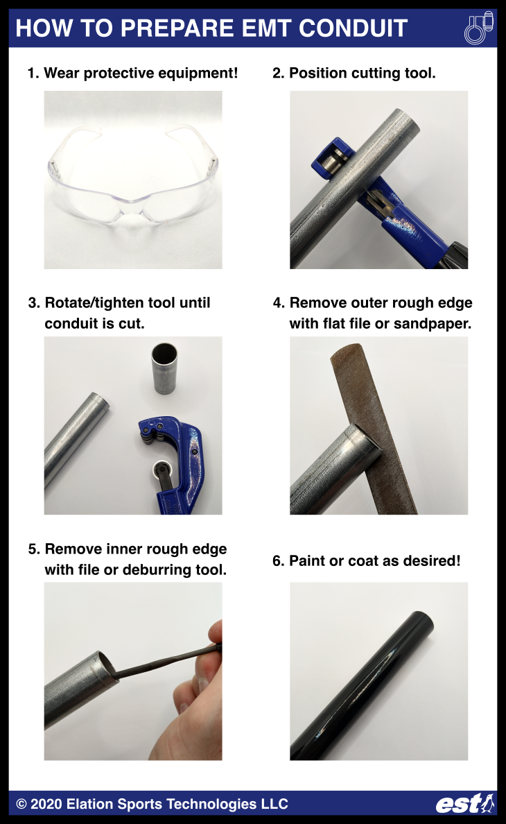
First, prepare the pieces of EMT conduit which will telescope inside of one another:
Wear protective equipment (e.g. safety glasses). Safety first!
Mark the desired cut length for the EMT conduit using a marker. For this article, we used three 5-foot lengths of 1", 3/4", and 1/2" EMT conduit.
Use a rotary cutting tool to cut the conduit to length.
Remove the sharp edge on the cut using a metal wire, or a rotary deburring tool or reamer.
Process the conduit as desired (paint, powder coat, etc.)
Assemble your telescoping pole - creating a telescoping pole from EMT conduit is easy using the telescoping coupling/clamp system from Elation Sports Technologies:
Press-fit the inner sleeve onto the smaller piece of conduit.
Install the injection-molded coupling/clamp onto the larger piece of conduit using a Phillips head screwdriver.
Extend the pole to the desired length by sliding the smaller piece of conduit, and then tightening the hand knob.

Next, we will install the strain gauges onto the telescoping pole and connect the electronics.
Strain Gauge Installation
Many videos and guides are available online demonstrating the procedure for installing strain gauges. To summarize - in order to install the strain gauges onto the telescoping pole:
Identify the position on the pole where it will be secured. The more securely the pole is held, the more accurate and repeatable the strain gauge sensor readings will be. The strain gauges must be located on the pole where it is free to flex. If the pole is held by hand, the strain gauges must be located past your hand grip location, towards the pole tip.
Clean the strain gauge area installation area by wiping it down with rubbing alcohol (Isopropanol, IPA) and allowing it to dry. Mark the installation area with 4 x marker lines to line up with the strain gauge. The strain gauges are to be installed in two pairs, with each pair's strain gauges located 180 degrees from one another on the conduit. That is, for each installed strain gauge, there is another gauge installed on the direct opposite side of the pole.
Add superglue to the installation area (gel-type superglue is recommended), and using your thumb, carefully press the strain gauge to bond it to the EMT conduit. Make sure that the strain gauge lies flat against the conduit, and that it is aligned lengthwise with the telescoping pole.
After the superglue has dried, solder flexible wire to the solder pads on each of the strain gauges, in preparation for connection with the rest of the electronics.

Circuit
The half-Wheatstone bridge wiring configuration used for this article is shared below. You will require two of these circuits (i.e. 4 x strain gauges, and 2 x HX711 amplifiers in total) in order to detect the magnitude and the direction of the force exerted at the telescoping pole tip.

The total circuit for the strain gauges is shared below (the diagram was created in KiCAD, a free and open-source electronic design software tool.) From left to right, the circuit consists of:
Arduino Nano powered by a USB-mini cable leading to your PC
2 x Sparkfun SEN-13879 HX711 amplifier boards
2 x half Wheatstone bridges for the strain gauges.
Each Wheatstone bridge requires the use of fixed resistors. In the diagram below, a 100Ω and 20Ω fixed resistor were combined to reach the required 120Ω fixed resistance value. 120Ω was selected for the fixed resistors because that was the approximate resistance value of the strain gauges we used. Measure your strain gauge resistance, and choose fixed resistor values to match it.

To make the electrical connections easier to connect and disconnect, JST-SM connectors were crimped onto the wires leading from the strain gauges to their HX711 amplifiers. The solder joints on the Sparkfun HX711 SEN-13879 amplifier boards were reinforced using black hot glue.
The Arduino Nano is mounted on a solderless breadboard, and the adhesive on the backside of that breadboard is attached to 2 x 3D printed mounts which are also used for the strain gauge amplifiers. The mount file can be downloaded on Thingiverse here. The clip was 3D printed using black PLA filament, with 100% infill to maximize the clip's durability.


Code
The Arduino Nano runs a code that continuously takes measurements from the strain gauge HX711 amplifiers, and it outputs that data using Serial protocol to a PC through a USB-mini cable. The PC runs a Python script that records the Arduino's output data. Alternatively, the Arduino software's Serial Monitor can be used to record that strain gauges' output data.
On the PC, Python is used to read and process the data. We use the Spyder IDE available through the Anaconda distribution for Python, but PyCharm or other Python development packages could also be used.
The following files are available for download from Github:
Arduino script - Sensing_Pole_Force_Clean.ino
Reads the HX711 strain gauge amplifiers and outputs that data over Serial (USB) to your PC.
Serial_Logger_Clean.py
Run on the PC using Python. This code logs the data output from the Arduino into a comma separated values (.CSV) file.
The script can be exited by pressing Cntl+C in the Python console.
Force-Sensing Telescoping Pole Calibration - Clean.py
This script reads the calibration data file that was created by the user. See the Calibration section of this article for instructions to create the Calibration file.
A sinusoid fit is made to the calibration data collected by the user, to obtain the fitting parameters (A, B, and D) as described in the Calibration section of this article.
The script also outputs a short CSV file containing the fitted function parameters.
Sensing Telescoping Pole Calibration Example - Clean.csv
Example calibration data file collected by the user. Replace the values in this file with your own calibration data.
Calibration_Data.csv
Output fit parameters from the example calibration.
Force-Sensing Telescoping Pole Demonstration - Clean.py
Processes data collected by Serial_Logger_Clean.py, and creates an animation for the pole tip force magnitude and direction. The animation is saved as a .MP4 video file.
Log_29Oct2021_1310PM.csv
Example of pole data collected, to be processed and animated
Calibration
The goal of calibration is to define a function that will take in a pair of readings for the 2 x strain gauge circuits, and output both the magnitude of the tip force, as well as the direction of that tip force. Here is the procedure to collect the data that will be used to define the calibration function:
Plug the Arduino into the PC, and verify that data is being received by the PC.
For a given pole length, record the Arduino readings when there is no external load on the tip, and the pole is only acting under its own weight. To do this, we held the pole horizontally at fixed hand positions, and recorded the Arduino output. Rotate the pole by 90 degrees - for each rotation position from 0 to 270 degrees, record the Arduino output.
Repeat step 2 under the same test conditions, except now adding a lateral load to the tip of the pole. For this experiment, we hung a 2.5 lb weight from the tip of the pole, as shown below.

The calibration data collected above is fed into a two equations to determine the fitting parameters (A, B, and D) that are used to relate the strain gauges' output (f_1 and f_2) to the tip force magnitude (F) and tip force direction (theta θ). Below, parameters B and E are the phase shifts for the first strain gauge pair and second strain gauge pair, respectively.
Each strain gauge pair varies sinusoidally in θ:
f_1 = A*F*L*sin(θ + B)
f_2 = D*F*L*sin(θ + E)
Combine the above two equations to obtain:
f_1*D*L*sin(θ + E) = f_2*A*L*sin(θ + B)
The two pairs of strain gauges have signals that are 90 degrees (pi/2 radians) out of phase with one another because of how they are positioned on the pole. Therefore:
E = B + pi/2
Substituting this expression for E back into the above equation yields:
f_1*D*L*cos(θ + B) = f_2*A*L*sin(θ + B)
Solve this equation for theta (θ) to get:
θ = arctan(f_1*D/(f2*A))
[Equation 1]
After the force angle theta has been solved, we can solve for the tip force magnitude F:
F=f_1/(A*L*sin(θ + B))
[Equation 2]
In a nutshell: After determining the fit parameters (A, B, and D) from the calibration step, input these fit parameters plus the strain gauge readings (f_1 and f_2) into Equation 1 above to determine the tip force direction (θ), and then Equation 2 can be solved to determine the tip force magnitude (F).
A diagram illustrating the relationship between the strain gauge readings with respect to the pole orientation θ is shared below. The red strain gauge pair #1 readings (f_1) and blue strain gauge #2 readings (f_2) each vary as a sinusoid with respect to θ, and the two sets of readings are offset from one another by a phase shift of 90 degrees.

With the calibration function and its coefficients defined, for a given telescoping pole length, we can determine the magnitude and direction of the tip force given the 2 x strain gauge readings!
Demonstration
Turn on the Arduino recording and output, and collect the readings of interest from the strain gauges. In this example, we pressed the tip of the telescoping pole against a pumpkin on a chair to demonstrate the sensing principle. The force and direction data are plotted below, and a video + animation is also shared:
Our demo video below can be found on the Elation Sports Technologies official Youtube channel!


The telescoping couplings used to create this project are available for purchase now from Elation Sports Technologies!
Also, check out our other blog posts for more inspiration for your next EMT conduit project!
Austin Allen
Founder and Owner
Elation Sports Technologies LLC


Comments