EMT Conduit-Mounted Weather Station Wind Sensors
- EST - Austin

- May 7, 2022
- 8 min read
Updated: May 15, 2022
Introduction
This article is part of a series discussing methods for adding sensing capabilities to a DIY telescoping pole project made from EMT conduit. Here I present a method for using simple off-the-shelf electronics to continuously measure (1) wind speed, and (2) wind direction as part of a custom weather station project. The demo video is shared below:
Weather stations (both commercially-available and do-it-yourself (DIY) feature one or more of the following sensing capabilities:
Wind speed (anemometer)
Wind direction (weather vane)
Air pressure (barometer)
Humidity (hygrometer)
Volume of rain (rain gauge)
Air temperature (thermometer)
Commercial weather stations available for online purchase are convenient, but are also often:
Expensive
Non-customizable
Near-impossible to interface with hobbyist controllers such as Arduino or Raspberry Pi
Regardless, these kinds of products are still sometimes the best option for home weather station projects - in those cases, a telescoping pole constructed from EMT conduit (readily available from hardware stores such as Home Depot or Lowes) made using a telescoping coupling can serve as a low-cost and study mount such all-in-one weather stations.
For all other situations where a DIY solution is more appropriate for your project, in this article we present a method to measure and log wind speed and wind direction using low-cost, off-the-shelf electronics and hardware. More functionality can be added to this platform with the optional electronics modules listed below.
Disclosure: Some of the links in this article are affiliate links. This means that, at zero cost to you, I will earn an affiliate commission if you click through the link and finalize a purchase.


Supplies
(Optional) 1 x Voxelab Aries FDM 3D printer
(Optional) 1 x 1.75mm black PLA filament
(Optional) 1 x Combined temperature + humidity sensor
(Optional) 1 x Air pressure sensor (barometer)
Telescoping Pole Setup
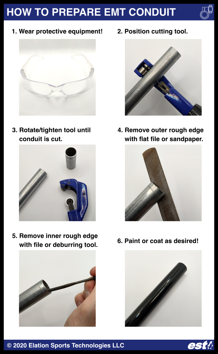
First, prepare the pieces of EMT conduit which will telescope inside of one another:
Wear protective equipment (e.g. safety glasses). Safety first!
Mark the desired cut length for the EMT conduit using a marker. For this article, we used three 5-foot lengths of 1", 3/4", and 1/2" EMT conduit.
Use a rotary cutting tool to cut the conduit to length.
Remove the sharp edge on the cut using a metal wire, or a rotary deburring tool or reamer.
Process the conduit as desired (paint, powder coat, etc.)
Assemble your telescoping pole - creating a telescoping pole from EMT conduit is easy using the telescoping coupling/clamp system from Elation Sports Technologies:
Press-fit the inner sleeve onto the smaller piece of conduit.
Install the injection-molded coupling/clamp onto the larger piece of conduit using a Phillips head screwdriver.
Extend the pole to the desired length by sliding the smaller piece of conduit, and then tightening the hand knob.

Additionally, for this project, in order to mount the wind speed and wind direction sensors on separate pieces of 1/2" EMT conduit, I utilized a conduit bender tool to bend and then cut to length an S-shaped piece of conduit. There are multiple video tutorials online detailing how to bend EMT conduit using this tool.

3D Printed Parts and Mounting the Electronics
To mount the electronics to the EMT conduit, I designed several custom 3D-printed parts, all of which can be found for free to download from Thingiverse (links are below):
I printed the parts using 100% infill on a Voxelab Aires 3D printer and 1.75mm diameter black PLA filament. The mechanical hardware used to mount the electronics are:
8 x M4 screw, 14mm length
8 x M4 hex nut
4 x 10-32 machine screw, 1/2" length
4 x 10-32 hex nut


An alternative method for mounting the S-shaped 1/2" EMT conduit piece to the telescoping conduit pole is to drill through both pieces of conduit and secure them using a 1/4"-20 bolt and nut.
Wiring
The wind speed and wind direction sensors are connected to the Arduino according to the wiring diagram below. They are supplied with 5V, and output an analog signal proportional to their measured quantities (i.e. wind speed or wind direction angle.)

I removed the caps from the wind sensors to see how they work. They each have a printed circuit board (PCB) mounted inside, with the primary sensor located on the top side, and the processing circuitry on the underside. Both styles of sensors used for this article output an analog output signal from 0 to 5V which updates approximately every 0.8 seconds, and which can be directly read by the Arduino. Other variations of the wind sensors are available for different voltage ranges, and for current or pulse output.
The wind speed sensor uses a break-beam/optical limit switch (photointerrupter) and plastic tabs on the rotating upper piece; when the sensor is blocked versus unblocked by the plastic tabs, a 5V pulse is detected and counted by the PCB, and the rate of those pulses correlates with the rotation speed, and thus the wind speed.


The wind direction sensor utilizes either a hall effect sensor, or a digital magnetic encoder, with a radially-polarized disc-shaped magnet mounted on the underside of the upper rotating portion of the wind sensor. The magnetic sensor is able to measure the magnetic field strength to determine the orientation of the radially-polarized magnet, which therefore tells us the direction that the wind is blowing. YouTuber James Bruton published a video illustrating this principle.


Code
Because the wind sensors refresh their output approximately every 0.8 seconds, the Arduino Nano must measure those analog signals slower or at that same rate. After taking those readings, the Arduino outputs them to a PC/laptop over Serial protocol via a connected USB-mini cable. Concurrently, the PC/laptop is running a Python script that logs the Arduino's output data. After collecting all the data of interest, a second Python script is used to produce an animation of the wind speed and direction as it varies over time.
The Arduino Nano analog readings range from 0 (meaning 0 volts) up to 1023 units (5 volts). The documentation for these generic wind speed and direction sensors is sometimes dubious, so I tested the sensors in order to calibrate them, to determine the relationship between their analog output to "real" units, i.e. wind speed in meters per second, and wind direction in degrees. I proceeded assuming that the output of these sensors is linear with respect to the quantity being measured.
To calibrate the wind speed sensor, I manually spun it and counted 20 rotations in 22 seconds, meaning an average rate of 0.909 rev/sec. This gave at average sensor output of 34.91 out of 1023 (i.e. 0.17 volts.) The radius from the center axis of the wind speed sensor to the center of any of its 3 x wind-catching "cups" is 65mm, so the corresponding circumference is 408.4mm, meaning that every revolution will travel 408.4mm. Finally, a rate of 0.909 rev/sec therefore corresponds to 408.4 * 0.909 = 371.28 mm/sec (0.371 meters.)
The wind direction sensor output was easier to calibrate. I manually turned the sensor, and The range of its output varied from 0 (at zero degrees) to 616 out of 1023 (i.e. 3.01V) at 359 degrees.
Therefore, the equations to convert the wind speed readings to m/s, and the wind direction readings to the direction in degrees, when reading the wind sensor analog outputs using an Arduino with a reading range of 0 to 5V:
Wind speed [meters per second] = (Arduino reading) * (1/34.91) * 0.371
Wind direction [degrees] = (Arduino reading) * (1/616) * 360


The wind sensors output their data no faster than once per 0.8 seconds. In order to create a smoother animation with a frame rate faster than once per 0.8 seconds, I interpolated the sensor data via a cubic spline fit. The wind direction data must be additionally processed before being fit with a cubic spline - this is because unlike the wind speed data, the wind direction data "loops," i.e. the difference between 0 and 359 degrees corresponds to a 616-unit jump in the sensor output.
A workaround to this problem is to attempt to track the net position change of the sensor output (i.e. attempt to determine the net rotations made by the sensor, clockwise or counterclockwise.) While not infallible, it is reasonable in most cases to assume that between consecutive data points, the most likely direction of movement is the one which results in the smallest net change in the sensor readings. For example, if the wind sensor outputs 0 degrees, and then the next reading is 359 degrees, it is more reasonable to assume that the sensor rotated clockwise by 1 degree rather than assume the sensor rotated counterclockwise by 359 degrees in that same amount of time. The faster the sensor readings are taken, the more likely this assumption becomes. I therefore iterated through each consecutive wind direction data point while applying this logic to decide the most likely direction of movement and thus track the net position of the wind direction over time.
The scripts and example data are available on GitHub:
Wind_Speed_And_Direction.ino
The code running on the Arduino Nano, which reads the data from the 2 x wind sensors.
The Arduino is connected to the PC/laptop via a USB-mini cable.
Serial_Logger_Clean.py
Python script running on PC, which logs all the data being output by the Arduino over Serial communication.
Outputs a comma separated values (CSV) file to save the logged data.
Log_27Apr2022_1608PM.csv
Example wind speed and direction data log file.
The data is, in order from left to right: timestamp in seconds, wind direction readings, and wind speed readings.
Wind Speed and Direction Sensing Demo - Clean.py
Processes the CSV file above to create an animation of the logged wind speed + direction data over time.
Demonstration
The wind sensors, Arduino and EMT conduit telescoping mounting pole took measurements outdoors for about 90 seconds. The raw data, and processed wind speed and wind direction data are presented below. The method for converting from the raw Arduino readings to the "real-world" data values is described in the previous section of this article. The raw data below illustrates how the wind direction data "loops" in the range of 0 to 616 units.


The wind direction data was processed to track the net position of the sensor over time.

The cubic split fit for the wind direction data is illustrated below by the dashed line. Performing a fit of the data in this way allows us to create smooth animations from the data, with a frame rate higher than the data output rate of the sensor (i.e. faster than once per 0.8 seconds.)

The final output video overlaid by an animation of the wind direction and wind speed readings is shared below, and it is also available directly on the official Elation Sports Technologies Youtube channel!
The telescoping couplings used to create this project are available for purchase now from Elation Sports Technologies!
Check out our other blog posts for more inspiration for your next EMT conduit project!
Austin Allen
Founder and Owner
Elation Sports Technologies LLC


Comments